So you want to go solar, but can’t decide between Lithium Iron Solar Batteries and Lead Acid Batteries. What’s the big deal?

Lithium Iron vs Lead acid batteries? In this post, we’ll discuss the difference between the two solar batteries:

  1. Small size and lightweight
  2. Battery usable capacity
  3. Long cycle life 
  4. Lifepo4 is safer than lead acid:
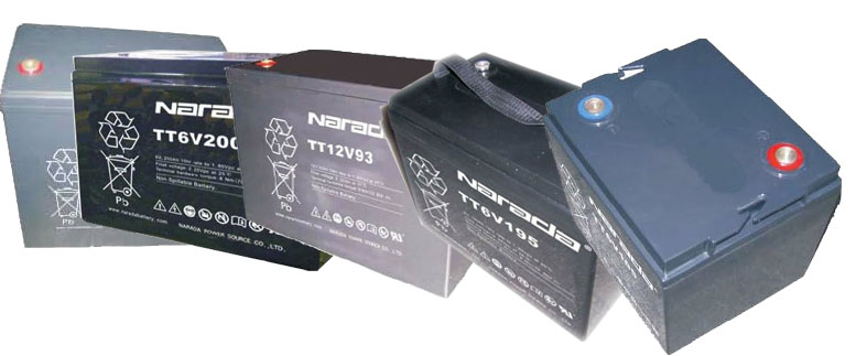
  5. Lead-acid batteries
  6. Lifepo4 battery characteristics

So you have heard of Lithium Iron phosphate (lifepo4 or LFP) batteries and are wondering whether they are worth the rage and raving?

Here are a few differences between lead acid batteries and lithium phosphate batteries to help you make a decision.

Lithium Solar Batteries Are Small in size and lightweight

Lead acid batteries take up more space than lithium iron phosphate batteries and when are mote difficult to wire up when you are connecting a large bank. The combined weight and volume occupied by lead acid batteries in a bank greater than a lifepo4 of equivalent capacity.

Solar Battery usable capacity

Below we can see that only a specific percentage of the battery can be used. We call this the Depth of discharge.

So a 100ah Lead acid is only 50-60% usable. Meaning it can be dropped to 40 or 50%.

Maximum daily depth of discharge (DoD) allowed **

  • Lithium-iron Phosphate = 80 to 90%

  • Lead-acid AGM = 15 to 30%

  • Lead-acid Gel = 20 to 40%

Lithium Solar Batteries Have a Long cycle life 

Lithium battery cycle life can be over 5000 times, which means a 10 to 20 year service life but the traditional lead-acid battery can be less than 1000 times which means 3 to 5 years.

A Lithium Iron battery is more efficient with energy when it uses it to charge or when it is running a load and therefore discharging. It is 90% efficient that a lead acid which is 70% efficient.

Lithium Solar Batteries / Lifepo4 are safer than lead acid

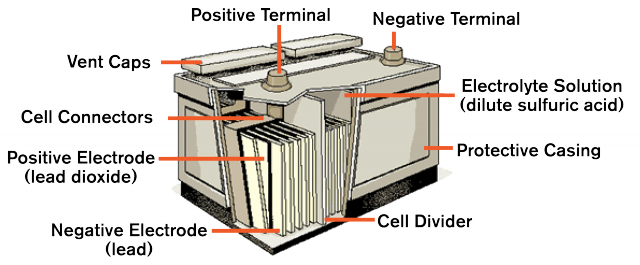
Lead-acid batteries contain heavy metals such as lead which is dangerous to the environment and wildlife. The battery will leak over time. Sulphuric acid Leaks may cause equipment corrosion and personal injury. Lithium iron phosphate batteries are safer as they do not contain any heavy metals and are non-toxic. The battery does not explode or ignite when punctured, overcharged or short circuited.

Lead-acid batteries

  1. The lead-acid battery does not fare well on demanding loads and grows weaker if the demands are constantly high.
  2. The battery is prone to self discharge when idle and can end up useless.
  3. It has problems in low-temperatures due to electrolytes freezing. The chemical reaction needed to create lead oxide cannot occur.
  4. The performance is greatly reduced over time.
  5. The batteries has fewer cycles and can not be charged and discharged indefinitely.
  6. Risk of explosion whem being overcharged.
  7. Leakages of acid and discharging of fumes or vapours.
  8. Short life span and low durability.

Lithium Solar Batteries/ Lifepo4 battery characteristics

  1. The battery can be charged and discharged at any time.
  2. The battery self-discharge is low, monthly self-discharge is less than 1%, the battery can be stored for a long time without discharging substantially.
  3. Uses a BMS system to charge and equalise batteries so they charge at an equal rate. Lead acid bayteries do not charge equally on most inverters and this damages them even when when they are not used much.
  4. Fast charging. Charges at a faster and higher rate than lead acid batteries.
  5. Discharge is more stable and does not drop in the way that a lead acid drops when it reaches certain voltages.

Lead acid battery technology is still improving and so we have not seen the end of lead acid batteries yet nor are we saying that LiFePo4 is the peak of battery technology. There is more to come. Lithium Iron batteries remain the most affordable batteries and value for money from an investment point. They are used by manufactures of electric cars all over the world including Tesla automobiles.

Take a look at our range of Lithium Iron batteries by clicking shop on our menu.

MPPT v PWM Solar Charge Controllers


What’s the Difference?

The two types of charge controllers most commonly used in today’s solar power systems are pulse width modulation (PWM) and maximum power point tracking (MPPT). Both adjust charging rates depending on the battery’s charge level to allow charging closer to the battery’s maximum capacity as well as monitor battery temperature to prevent overheating.

solar charge controller
PWM solar charge controller

Comparing the Two
If maximizing charging capacity were the only factor considered when specifying a solar controller, everyone would use a MPPT controller. But the two technologies are different, each with it’s own advantages. The decision depends on site conditions, system components, size of array and load, and finally the cost for a particular solar power system.

Temperature Conditions
An MPPT controller is better suited for colder conditions. As solar module operating temperature goes down, the Vmp1 increases. That’s because the voltage of the solar panels operating at their peak power point at Standard Testing Conditions (STC is 25C°) is about 17V while the battery voltage is about 13.5V. The MPPT controller is able to capture the excess module voltage to charge the batteries.  As a result, a MPPT controller in cool conditions can produce up to 20 – 25% more charging than a PWM controller.

In comparison, a PWM controller is unable to capture excess voltage because the pulse width modulation technology charges at the same voltage as the battery. However, when solar panels are deployed in warm or hot climates, their Vmp decreases, and the peak power point operates at a voltage that is closer to the voltage of a 12V battery. There is no excess voltage to be transferred to the battery making the MPPT controller unnecessary and negating the advantage of an MPPT over a PWM.

mppt solar charge controller
Ipanda_power_factory_Lcd_Led_48v_mppt

Array to Load Ratio
In a scenario where the solar array is large relative to the power draw from the batteries by the load, the batteries will stay close to a full state of charge. A PWM controller is capable of efficiently maintaining the system without the added expense of an MPPT controller.

Size of the System
Low power systems are better suited to a PWM controller because:

  • A PWM controller operates at a relatively constant harvesting efficiency regardless of the size of the array
  • A PWM controller is less expensive that a MPPT, so is a more economical choice for a small system
  • A MPPT controller is much less efficient in low power applications. Systems 170W or higher tickle the MPPT’s sweet spot

Type of Solar Module
Stand-alone off-grid solar modules are typically 36-cell modules and are compatible with both PWM and MPPT technologies. Some grid-tie solar modules on the market today are not the traditional 36-cells modules that are used for off-grid power systems. For example, the voltage from a 60-cell 250W panel is too high for 12-Volt battery charging, and too low for 24-Volt battery charging. MPPT technology tracks the maximum power point (thus MPPT) of these less expensive grid-tie modules in order to charge the batteries, whereas PWM does not.

Cost
MPPT controllers are typically more expensive than PWM’s but are more efficient under certain conditions, so they can produce more power with the same number of solar modules than a PWM controller. One must then analyze the site to verify that the MPPT can indeed perform more efficiently when used in that system’s given set of conditions.

When specifying one technology over the other, the cost of the controller becomes less important than the total cost of the system. To specify a controller technology simply based of cost, be sure to perform a close analysis of realized efficiencies, system operation, load and site conditions.

SUMMARY OF COMPARISON

  PWM Charge Controller MPPT Charge Controller
Array Voltage PV array & battery voltages should match PV array voltage can be higher than battery voltage
Battery Voltage Operates at battery voltage so it performs well in warm temperatures and when the battery is almost full Operates above battery voltage so it is can provide “boost” in cold temperatures and when the battery is low.
System Size  Typically recommended for use in smaller systems where MPPT benefits are minimal ≈ 150W – 200W or higher to take advantage of MPPT benefits
Off-Grid or Grid-Tie Must use off-grid PV modules typically with Vmp ≈ 17 to 18 Volts for every 12V nominal battery voltage Enables the use of lower cost/grid-tie PV Modules helping bring down the overall PV system cost
Array Sizing Method PV array sized in Amps (based on current produced when PV array is operating at battery voltage) PV array sized in Watts (based on the Controller Max. Charging Current x Battery Voltage)

 ________________________

1 The Vmp (maximum power voltage) is the voltage where the product of the output current and output voltage (amps * volts) is greatest and output power (watts = amps * volts) is maximized. Module wattage ratings (e.g. 100W, 205W) are based on Pmp (maximum power) at Vmp under standard test conditions (STC).


source:http://solarcraft.net/articles/comparing-pwm-and-mppt-charge-controllers/
Steps for measuring duty cycle.

How to measure duty cycle

  1. Set the digital multimeter (DMM) to measure frequency. The steps can vary by meter. Usually a multimeter’s dial will be turned to dc V (dc V) and the Hz button is pressed. The DMM is ready to measure duty cycle when a percent sign (%) appears in the right side of the multimeter’s display.
  2. First insert the black test lead into the COM jack.
  3. Then insert the red lead into the V Ω jack. When finished, remove the leads in reverse order: red first, then black.
  4. Connect the test leads to the circuit to be tested.
  5. Read the measurement in the display. A positive symbol (+) indicates POSITIVE time percent voltage measurement. A negative symbol (-) indicates NEGATIVE time percent voltage measurement.Note: A positive reading typically indicates a circuit’s ON time and a negative reading its OFF time. On occasion a negative portion of the signal can create an ON signal.
  6. Press the beeper button (beeper button) to toggle between POSITIVE time and NEGATIVE time percent voltage measurement. Note: The button used varies by digital multimeter. Refer to you model’s user manual for specific instructions.

Duty cycle basics

  • Duty cycle is the ratio of time a load or circuit is ON to the time a load or circuit is OFF. A load that is turned ON and OFF several times per second has a duty cycle.
  • Why do this? Many loads are rapidly cycled on and off by a fast-acting electronic switch to accurately control output power at the load. Lamp brightness, heating element outputs and magnetic strength of a coil can be controlled by duty cycle.
  • Duty cycle is measured in percentage of ON time. Example: A 60% duty cycle is a signal that is on 60% of the time and off 40% of the time.
  • An alternate way to measure duty cycle is dwell, measured in degrees instead of percent.
  • When measuring duty cycle, a digital multimeter displays the amount of time the input signal is above or below a fixed trigger level – the fixed level at which the multimeter counter is triggered to record frequency. Slope is the waveform edge on which the trigger level is selected.
  • The percent of time above the trigger level is displayed if the positive trigger slope is selected. Conversely, the percent of time below the trigger level is displayed if the negative trigger slope is selected. The slope selected is indicated by a positive (+) or negative (-) symbol in the display. Most multimeters default to display the positive trigger slope; the negative trigger slope is usually selected by pressing an additional button. Refer to a DMM’s user manual for specifics.

DMM

Reference: Digital Multimeter Principles by Glen A. Mazur, American Technical Publishers.


There are three main types of photovoltaic solar panels for both commercial and residential use.

They are:

  1. Monocrystalline
  2. Polycrystalline
  3. Amorphous Silicon also called “Thin Film”


All three types of solar panels have both advantages and disadvantages depending on the end user’s budget, the size and type of environment where they are used and the expected output of the system to name a few.


Monocrystalline Photovoltaic Solar Panel

mono_solar


Made from a large crystal of silicon.  Monocrystalline solar panels are the most efficient and most expensive panels currently available.  Because of their high efficiency, they are often used in applications where installation square footage is limited, giving the end user the maximum electrical output for the installation area available.


Polycrystalline Photovoltaic Solar Panel

 solar-panel-installation

Characterized by its shattered glass look because of the manufacturing process of using multiple silicon crystals, polycrystalline solar panels are the most commonly seen solar panels.  A little less efficient than monocrystalline panels, but also less expensive.


Amorphous Silicon “Thin Film” Photovoltaic Solar Panel

 thin_film_amorphous_silicon_Photovoltaic_solar_panel

These panels can be thin and flexible which is why they are commonly referred to as “Thin Film” solar panels.  Amorphous silicin solar panels are common for building integrated photovoltaics (BIPV) applications because of their many application options and aesthetics.  They are cheaper and are not effected by shading. Drawbacks are low efficiency, loss of wattage per sq. ft. installed and heat retention.


They can be manufactured using silicon, copper indium diselenide (CIS) or cadmium telluride (CdTe).


A car’s battery is designed to provide a very large amount of current for a short period of time. This surge of current is needed to turn the engine over during starting. Once the engine starts, the alternator provides all the power that the car needs, so a car battery may go through its entire life without ever being drained more than 20 percent of its total capacity. Used in this way, a car battery can last a number of years. To achieve a large amount of current, a car battery uses thin plates in order to increase its surface area. A deep cycle battery is designed to provide a steady amount of current over a long period of time. A deep cycle battery can provide a surge when needed, but nothing like the surge a car battery can. A deep cycle battery is also designed to be deeply discharged over and over again (something that would ruin a car battery very quickly). To accomplish this, a deep cycle battery uses thicker plates. Typically, a deep cycle battery will have two or three times the RC of a car battery, but will deliver one-half or threequarters the CCAs. In addition, a deep cycle battery can withstand several hundred total discharge/recharge cycles, while a car battery is not designed to be totally discharged.

First understand your Power Requirement

One of the most important factors that you need to know before buying an inverter is how much power you need to run your electrical appliances such as your tv, lights, satellite or fridge. This will help you determine what size inverter to buy and how many batteries to bank.

Suppose you want 3 Fans, 3 Tube lights, 1 CFL & 1 television to operate at the time of power failure. Below is the power consumed by these items:

1 Fan – 70 Watts

1 tube light – 60 watts

1 CFL – 25 watts

1 Television – 120 watts

Therefore your total power requirement is ( 3*70 +3*60 + 25 + 120) = 535 watts

Find the VA rating of the inverter you need

It stands for the Volt ampere rating. It is the voltage and current supplied by the inverter to the equipments. If an inverter operates with 100% efficiency, then the power requirement of the electrical items and power supplied by inverter is same. But we all know that 100% or ideal conditions don’t exist in real.  Most  inverters have the efficiency range from 60 % to 80%. This efficiency is also called power factor of an inverter and is simply  the ratio of power required by the appliances to power supplied by an inverter. Power factor of most inverters ranges from 0.6 to 0.8.

Hence Power supplied (or VA rating of inverter) = Power requirement ( power consumed by equipments in watts) / Power factor( efficiency).

Here average value of power factor or efficiency  is considered i.e. 0.7

Power of inverter (VA) = 535/0.7 = 765 VA

In the market 800 VA inverters are available. So an inverter with 800 VA will be the right choice for your home.

TT Main

Know the battery your inverter needs

 Battery is the backbone of an inverter system. The performance and life of an inverter largely depend upon the battery quality. The next big question is how long will your batteries last? This is what we call the battery capacity. It is the battery capacity that decides how long your inverter will provide power to your appliances. Battery capacity is measured in AH which stands for Ampere Hours. Basically how many amperes will the battery discharge every hour of use. a 100AH battery with a discharge of 5 amps will last 20 hours.

This is how we determine how many batteries are needed:

Battery capacity = Power requirement  (your load in watts) x Duration or runtime ( hours) / Battery Voltage (12v)

Battery Capacity = (535 watts x 3hrs) / 12v = 133 Ah

** Value of Battery voltage is taken 12V

Therefore a battery with a capacity of 130 Ah will work for you.

So if you want to run 3 fans, 3 tube lights , 1 CFL and 1 TV for 3 hours during power failure you would need 800VA inverter and 130 Ah battery.

By understanding this simple calculation you not only save yourself from the misleading information shared by inverter dealers but also  help yourself in taking correct decision.

GELLED ELECTROLYTEFIAAM


Advantages

  • Totally maintenance free
  • Superior deep cycle life when compared to AGM
  • Air transportable
  • Spill proof/leak proof
  • Minimal corrosion thus physically compatible with sensitive electronic equipment
  • Installs upright or on side
  • Very low to no gassing (unless overcharged)
  • Superior shelf life when compared to Wet Cell
  • No recharge current limitation @ 13.8 volts
  • Rugged and vibration-resistant
  • Very safe at sea with no chlorine gas in bilge (due to sulfuric acid and salt water mixing)
  • Most versatile: Starting. Deep Cycle, Stationary
  • Lowest cost-per-month (cost / months of life)
  • Lowest cost-per-cycle (cost / life cycles)

Disadvantages

  • Higher initial cost
  • Water cannot be replaced if continually overcharged
  • Voltage-regulated chargers must be used
  • Charge voltage must be limited to extend life (13.5 to 13.8 volts maximum at 68°F)

—————————————————————————————

(AGM) ABSORBED ELECTROLYTElead-acid-battery_diagram wet battery

Advantages

  • Ideal for standby or back-up applications
  • Higher charge and discharge currents
  • Totally maintenance-free
  • Air transportable
  • Spill proof/ Leak proof
  • Minimal corrosion thus physically compatible with sensitive electronic equipment
  • Installs upright or on side
  • Lower cost than gel cell batteries
  • Very low to no gassing (unless overcharged)
  • Excellent for starting and stationary applications
  • Superior for shorter duration/higher discharges

Disadvantages

  • ½ the cycle life of Gel or flooded Wet Cell in deep cycle applications
  • Charge voltage must be limited (14.1 to 14.4 volts maximum at 68°F )
  • Voltage-regulated chargers must be used
  • Water cannot be replaced if continually overcharged

—————————————————————————————

WET CELL (FLOODED ELECTROLYTE) wet cell battery

Advantages

  • Lowest initial cost
  • Water can be added (if accessible)
  • Excellent for higher current applications
  • Certain designs are good for deep cycle applications
  • Replacements readily available

Disadvantages

  • Spillable
  • Operates upright only
  • Emits corrosive Gases and thus cannot be installed near sensitive electronic equipment
  • Cannot be installed near sensitive electronic equipment
  • Maintenance required (if accessible)

There is not one single battery that is suited for all applications or weather conditions. Instead an evaluation will help determine the battery that is best suited for the site conditions and application. Consult with Caprica Solar to ensure your system’s integrity and the safety of those who operate them.

Gel vs. AGM vs. Wet Cell Batteries


One of the most important decisions when designing a stand-alone power system is deciding the best battery for the application. Gathering information about the site’s maximum summer and lowest winter temperatures, the duration of extreme conditions, accurate load and duty-cycle information, and charge and discharge cycles are all key factors in battery selection.

Failure to make the right decision based on area classifications, power cycle life, maximum environmental temperatures, and maximum low temperatures are all factors that can lead to safety issues, the early death of a battery, and the unexpected failure/loss of control, measurement, communications, or UPS systems. Be sure to consult a specially trained technician to design stand-alone power systems using the following information as a guide.

Gel Cell, Absorbed Glass Mat (AGM), and Wet Cell are various versions of lead acid batteries. The Wet comes in two styles: serviceable, and maintenance free. Gel Cell and the AGM batteries are specialty batteries that typically cost twice as much as a premium Wet Cell battery. However, Gel cell and AGM batteries do not tend to sulfate or degrade as easily as Wet Cell. As a result, there is little chance of a hydrogen gas explosion, or corrosion of electrical components and wiring in close proximity when using these batteries. In most cases AGM batteries will give longer life span and greater cycle life than a Wet Cell battery.

What is the difference between Gel Cell and “(AGM)” Absorbed Electrolyte batteries?

AGM batteries are typically good deep cycle batteries and they deliver their best life performance if recharged before the battery drops below the 50 percent discharge rate. These batteries typically have a shorter life cycle than Gel Cell batteries (as much as ½). They are often best used in applications requiring higher charge and discharge currents such as those in a UPS backup power system.

The recharge voltages of Gel Cells are lower than the other styles of lead acid battery. Gel Cell batteries are best used in very deep cycle application and may last a bit longer in hot weather conditions. The selection of battery chargers with Gel Cell batteries is critical because using an incorrect battery charger with a Gel Cell battery will cause poor performance and premature battery failure.

What is the difference between Gel Cell/AGM and traditional Wet Cell batteries?

Wet Cells contain liquid electrolyte that can spill if tipped or punctured, causing corrosion to affected areas. Therefore, they are not air transportable without special containers. They cannot be shipped via UPS or Parcel Post, and should not be used near sensitive electronic equipment. They can only be installed “upright.”

Can Gel Cells be installed in sealed battery boxes?

NO! Never install any type of battery in a completely sealed container. Although the normal gasses (oxygen and hydrogen) produced in a Gel Cell battery will recombined and not escape, oxygen and hydrogen can escape from the battery in an overcharged condition (as is typical in any type battery).

For safety’s sake, these potentially explosive gasses must be allowed to vent to the atmosphere and must never be trapped in a sealed battery box or tightly enclosed space.


Tags: articles
× Help